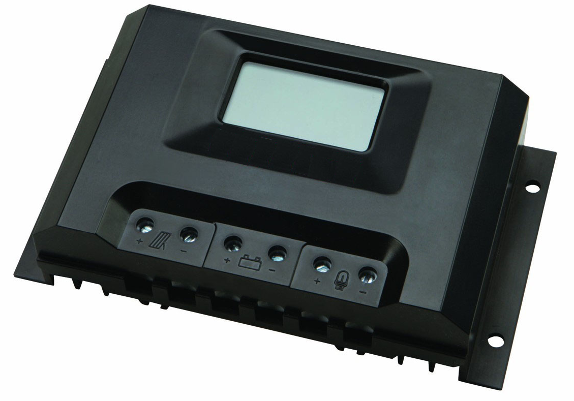
PWM Solar Charge Controller
PWM Based Solar Charge Controller
The solar charge controller is used in off-grid and grid-tie with battery backup systems. The charge controller is an electronic voltage regulator that is used to limit the rate at which electric current is drawn in or out of the batteries. The simplest charge controllers turn off the charge when the battery reaches the optimum charging point and turns on when it goes below certain level. It fully charges the battery without permitting overcharge while preventing from reverse current flow. The overcharge or overvoltage may reduce the battery performance or lifespan and may pose a safety risk.
l. Technical Specifications:
|
|
Product Rating |
12/24 V , 20 A( 12 / 24 V selection using Switch ) |
12/24 V , 40 A( 12 / 24 V selection using Switch ) |
|
1 |
Nominal SPV input voltage |
12/24 V DC |
12/24 V DC |
|
2 |
Max. SPV input voltage |
55 V DC |
55 V DC |
|
3 |
Nominal SPV input current |
15.0 Ampere |
35.0 Ampere |
|
4 |
Max. SPV input current |
20.0 Ampere |
40.0 Ampere |
|
5 |
Max. Load Current |
16.0 Amp |
35.0 Amp |
|
6 |
Self Consumption |
< 30 mW @ 25 °C |
< 30 mW @ 25 °C |
|
7 |
Float Charge |
13.7 V DC @ 25°C in 12V mode 27.4 V DC @ 25°C in 24V mode |
13.7 V DC @ 25°C in 12V mode 27.4 V DC @ 25°C in 24V mode |
|
8 |
Boost Charge |
14.4 V DC @ 25°C,2h in 12V mode 28.8 V DC @ 25°C,2h in 24V mode |
14.4 V DC @ 25°C,2h in 12V mode 28.8 V DC @ 25°C,2h in 24V mode |
|
9 |
Equalisation |
14.7V ( 12 V mode ) 29.4V (24 V mode ) For every 10 complete cycles @ 2.45 V per cell ( can be customised as per Battery specs ) |
14.7V ( 12 V mode ) 29.4V (24 V mode ) For every 10 complete cycles @ 2.45 V per cell ( can be customised as per Battery specs ) |
|
10 |
Charging Technology |
PWM with Boost, Float and Equalize modes |
PWM with Boost, Float and Equalize modes |
|
11 |
Load Disconnect Voltage |
10.8 V in 12 V mode 21.6 V in 24 V mode |
10.8 V in 12 V mode 21.6 V in 24 V mode |
|
12 |
Load Reconnect Voltage |
12.2 V in 12 V mode 24.4 V in 24 V mode |
12.2 V in 12 V mode 24.4 V in 24 V mode |
|
13 |
Battery Low voltage cut-off |
10.8 V in 12 V mode 21.6 V in 24 V mode Optional Load current compensation for cut-off voltage value variation. |
10.8 V in 12 V mode 21.6 V in 24 V mode Optional Load current compensation for cut-off voltage value variation. |
|
14 |
Battery Type |
Gel / Sealed / Flat paste flooded |
Gel / Sealed / Flat paste flooded |
|
15 |
Recommended Battery Capacity |
12V,100AH or 24V,100AH |
12V,100AH or 24V,100AH |
|
16 |
Operating Environment |
-20 °C to +60 °C |
-20 °C to +60 °C |
|
17 |
Temperature Compensation |
-5 milli Volt / °C / Cell |
-5 milli Volt / °C / Cell |
|
18 |
Efficiency |
˃ 98% @ 25 °C |
˃ 98% @ 25 °C |
II. Protections
|
|
Solar Terminal |
Battery Terminal |
Load Terminal |
|
Reverse Polarity |
YES ( Solid State ) |
YES (Solid State ) |
-NA- |
|
Short circuit |
YES |
YES (Software based) |
YES (Software based) |
|
Over current |
YES (Software based) |
YES (Software based) |
YES (Software based) |
|
Reverse Current |
YES |
YES |
-NA- |
|
Over Voltage |
YES (Software based) |
YES (Software based) |
-NA- |
|
Under Voltage |
YES (Software based) |
YES (Software based) |
-NA- |
|
Over Temperature |
-NA- |
-NA- |
-NA- |
III. Indications
|
LED |
Status |
Function |
|
Solar Charging RED LED Indicator |
On |
During BOOST charging state |
|
Flash |
During FLOAT charging state |
|
|
Off |
Under Non-availability of SOLAR Power |
|
|
Battery SOC GREEN and RED LED Indicators |
RED ON |
Under LOW BATTERY condition |
|
GREEN ON |
Under FULL Charge condition |
|
|
Load YELLOW LED Indicator |
On |
When LOAD can be connected |
|
Off |
When LOAD cannot be used |
|
|
Mode indication LED(Amber) |
On |
During Inverter integration(for selecting charging mode) |
|
|
Off |
Only solar charge available |
|
Fault Indication |
Blinking All LED’S |
During fault condition |
IV.Selection Switches:
1. 2-Switches are provided for Battery type selection.
2. 1-Switch for selecting 12V/24V mode.
3. 1-Switch for selecting mode during inverter Integration.